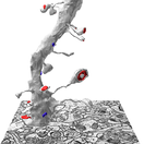
 KH Lab
Lab 1.2: The Postsynaptic Density
Overview
Synapses can be identified by the darkly staining postsynaptic density (PSD) in the postsynaptic dendrite and the vesicles in the presynaptic axon. A trace of the PSD area gives the area of the synapse. In the electron microscope image below, the red arrows point at the PSDs in dendritic spine heads; vesicles are visible in the presynaptic axons next to them.

This lab builds on the spines you traced in Lab 1.1: you add the synapses to them. These are the names of the traces you will add:
| Spine (from Lab 1.1) | Synapse quantification (cfa = contact flat area) | Synapse visualization (c = contact) |
|---|---|---|
| d03sp06 | d03cfa06 | d03c06 |
| d03sp32 | d03cfa32 | d03c32 |
| d03sp47 (branch a) | d03cfa47a | d03c47a |
| d03sp47 (branch b) | d03cfa47b | d03c47b |
Before the tracing steps, this handout reviews the three ways a PSD can be oriented in 3D, and how each one looks on a single EM section. The same object can look different in 2D depending on the cutting plane. The PSDs you trace in this lab are all cross-sectioned PSDs. They are the simplest to trace, and they show most clearly how synapse size is calculated.
Three types of PSD orientation
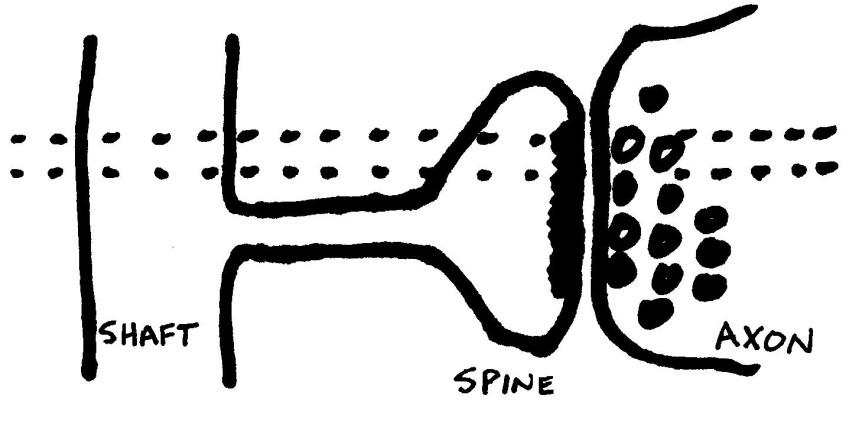
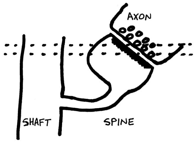
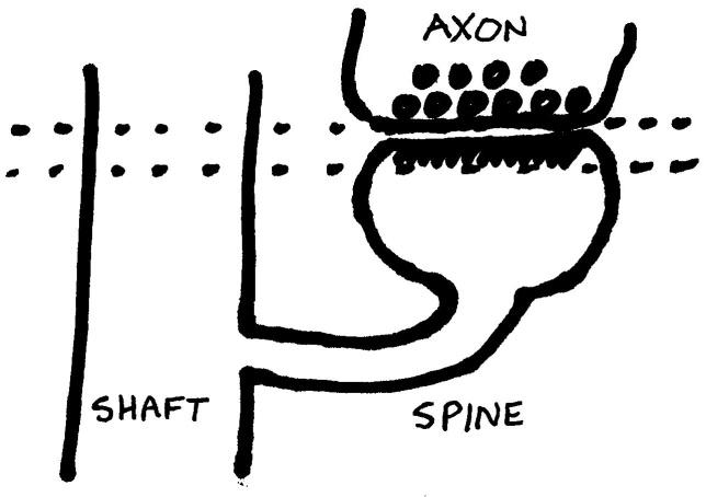
In the cartoons below, the dashed lines mark a single section (sections are typically around 50 nm thick; the drawings are not to scale). Depending on how the spine is oriented to the shaft, a synapse can be cut in different orientations. (Shoddy Sharpie cartoons by P.H. Parker.)
1. Cross section
Cross-section PSDs occur when the section is cut perpendicular to the synapse. Sometimes you can clearly see the synaptic cleft between the spine and axon membranes. Right: EM image of a spine (S) with a perfectly cross-sectioned synapse (SynapseWeb Atlas, 1.6.04).

2. Oblique
Oblique PSDs occur when the section is cut at an angle to the synapse, so that the PSD "slopes" across more than one section.
3. En face
En face PSDs occur when the section is cut parallel to the synapse, so that the entire "face" of the synapse is visible in one section. The entire PSD is contained in that section. En face is a French phrase meaning "opposite" or "across the street".
Two types of tracing tools
PyReconstruct has two basic tracing tools: closed and open. The Closed Trace tool draws closed traces either freehand (Scribble) or point by point (Poly); see Lab 1.1 to set it up. You need both open and closed traces to trace synapses.
| Tracing tool | Purpose | Flat area calculation | Tool icon |
|---|---|---|---|
| Closed Trace (C) | Closed traces (like circles) | Area of the closed trace |  |
| Open Trace (O) | Open traces (like lines) | Length times section thickness |  |
Two types of PSD traces: contact vs contact flat area
Here "contact" means synaptic contact.
- Contact traces (c-traces, red) make a 3D reconstruction of where the PSD sits on the dendrite.
- Contact flat area traces (cfa-traces, green) measure the synaptic area.
| Trace name | Purpose | Color | Tool |
|---|---|---|---|
| d##c## | 3D visualization in PyReconstruct | red | Closed Trace |
| d##cfa## | Synapse area calculation | green | Open Trace |
Set up a palette square for each trace name:
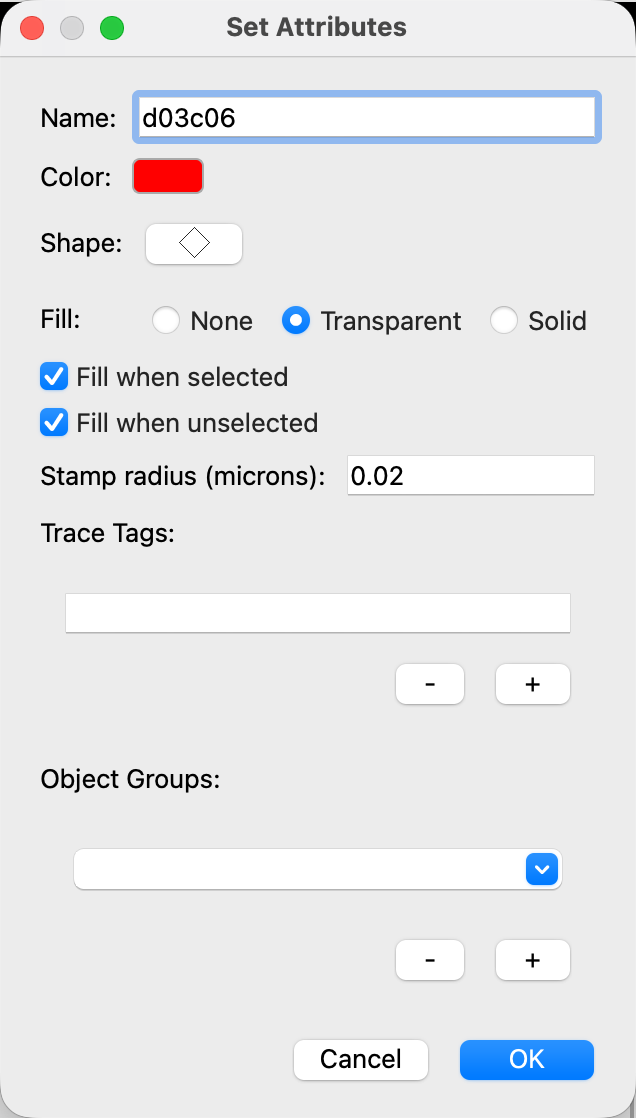
- Right-click an unused palette square. The Set Attributes dialog opens.
- In Name, type
d03c06. - Click Color and choose red.
- In Fill, choose Transparent, and click OK.
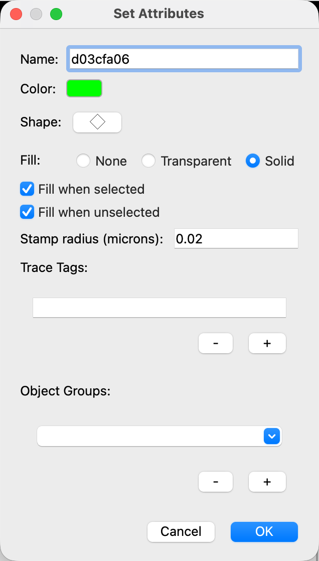
- Right-click another unused palette square.
- In Name, type
d03cfa06, choose green in Color, choose Solid in Fill, and click OK. - Do the same for the other names in the table above (d03c32 and d03cfa32, d03c47a and d03cfa47a, d03c47b and d03cfa47b).
Trace one PSD
Do this on every section where the PSD of your spine is visible, starting with d03sp06:
- Go to the first section where the PSD appears.
- Click the d03cfa06 palette square.
- Click the Open Trace tool (O).
- Drag along the length of the PSD, and let go to finish the green cfa-trace.
- Click the d03c06 palette square.
- Click the Closed Trace tool (C).
- Draw a red c-trace around the cfa-trace. Let it extend just outside the spine membrane, slightly into the axon.
- Go to the next section (Page Up) and repeat steps 2 to 7, until the PSD is no longer visible.
Then do the same for d03sp32 and for both branches of d03sp47.
Tracing PSDs: cross-sectioned
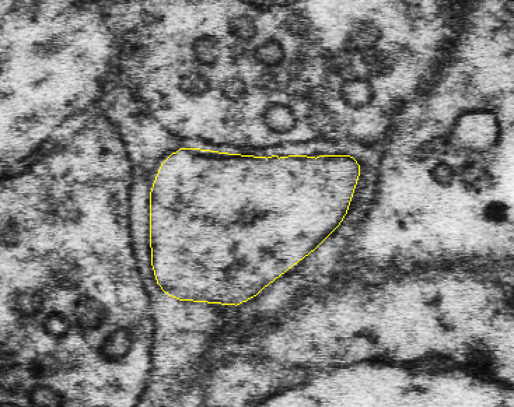
The images below show one cross-sectioned PSD on five sections in a row: the spine trace (yellow), the c-trace for the 3D reconstruction (red), and the cfa-trace for the synapse flat area (green). (Example from this series: spine d03sp28_branched, sections 81 to 85.)
Section 1: No PSD.
Section 2: The PSD is traced with an open cfa-trace line (green) along the length of the PSD. The cfa-trace is enclosed by a closed c-trace (red) that extends outside the spine membrane and slightly into the axon.
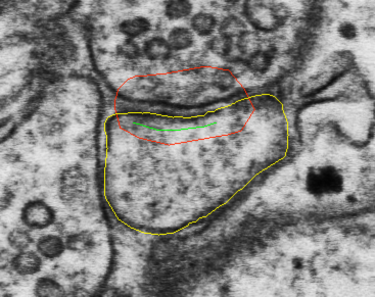
Sections 3 and 4: Traced the same way on each section.
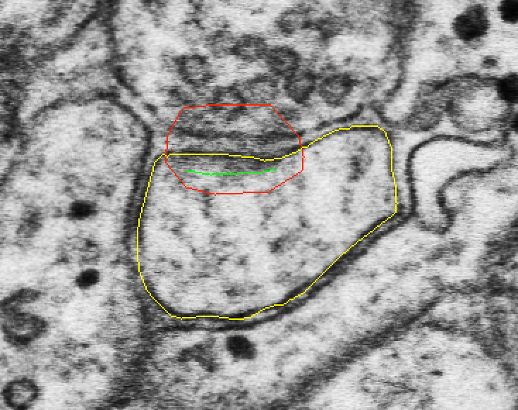
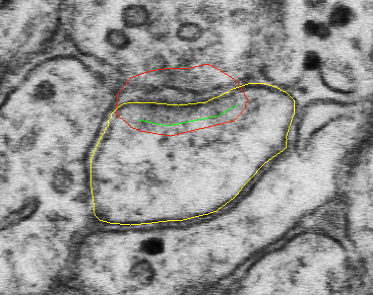
Section 5: The PSD is no longer visible, so no traces are added. This is the end of the PSD.
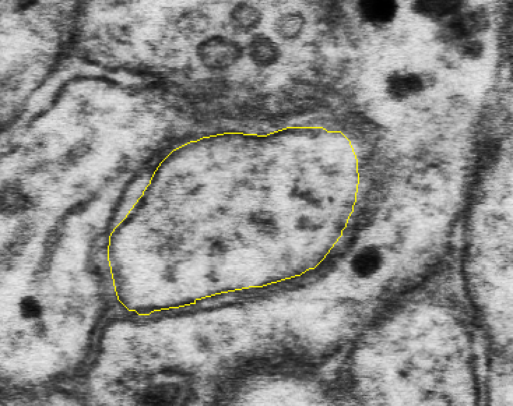
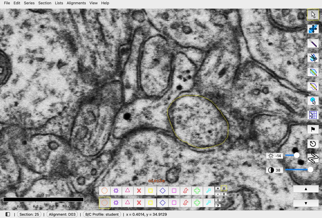
In the class series: spine d03sp05 on sections 25 to 30, with d03c05 (red) and d03cfa05 (green) on sections 26 to 29.
Calculating flat area of synapses
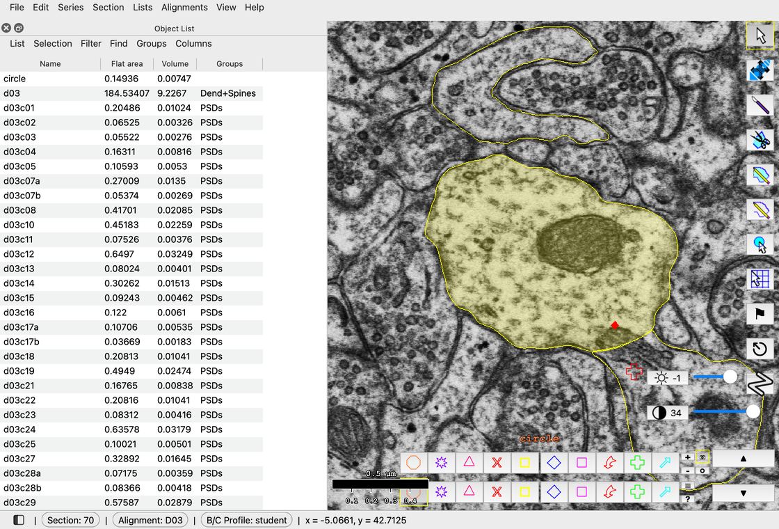
Filter > Regex filter... > d03cfa.* > OK.
- Go to Lists > Object list (Ctrl+Shift+O; Mac: Cmd+Shift+O).
- In the Object List, click Filter > Regex filter....
- Replace
.*withd03cfa.*and click OK. The list shows every cfa object on d03: the synapses that were already traced, plus yours. -
Read the flat area of each synapse in the Flat area column. The unit is square micrometers (µm²). Be sure you read Flat area, not Volume.
If you do not see a Flat area column, click Columns > Set columns... in the Object List, check Flat area, and click OK.
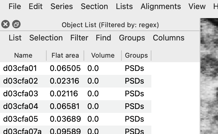
The Object List filtered by d03cfa.* -
To save the list, click List > Export... in the Object List, choose a file name, and save. The file is a comma-separated values file (.csv) that opens in Excel. You can also select flat area values in the Object List, press Ctrl+C (Mac: Cmd+C) to copy them, and paste them into a spreadsheet.
For a cross-sectioned synapse, flat area is the length of the cfa-trace times the section thickness. In general:
Flat area = Σall sections [Σopen traces length × thickness + Σclosed traces area]
References
- Legacy Reconstruct User Manual, Chapter 9, p. 106.
- SynapseWeb Atlas, 1.6.04.